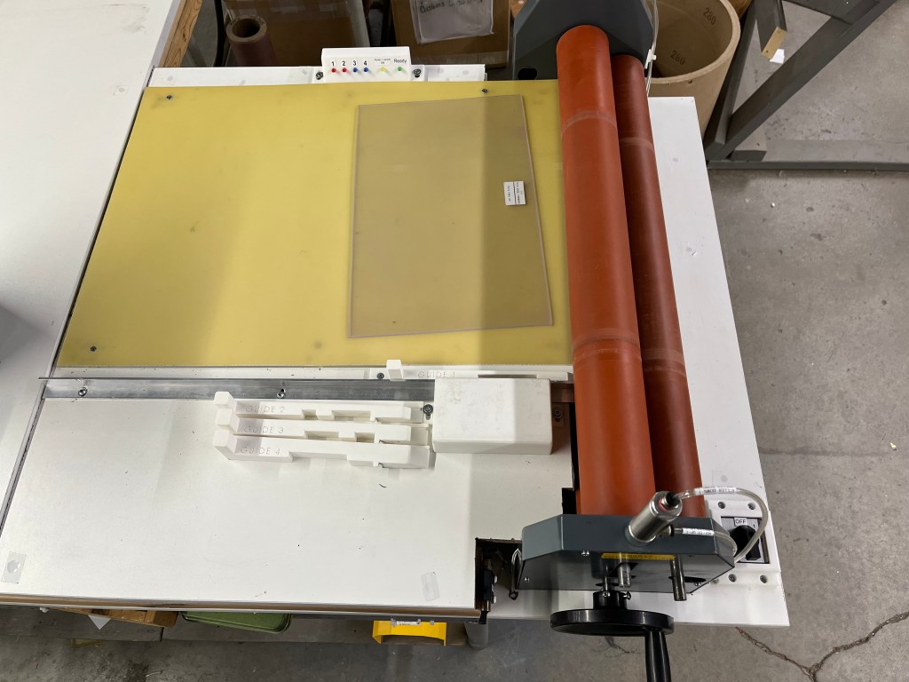
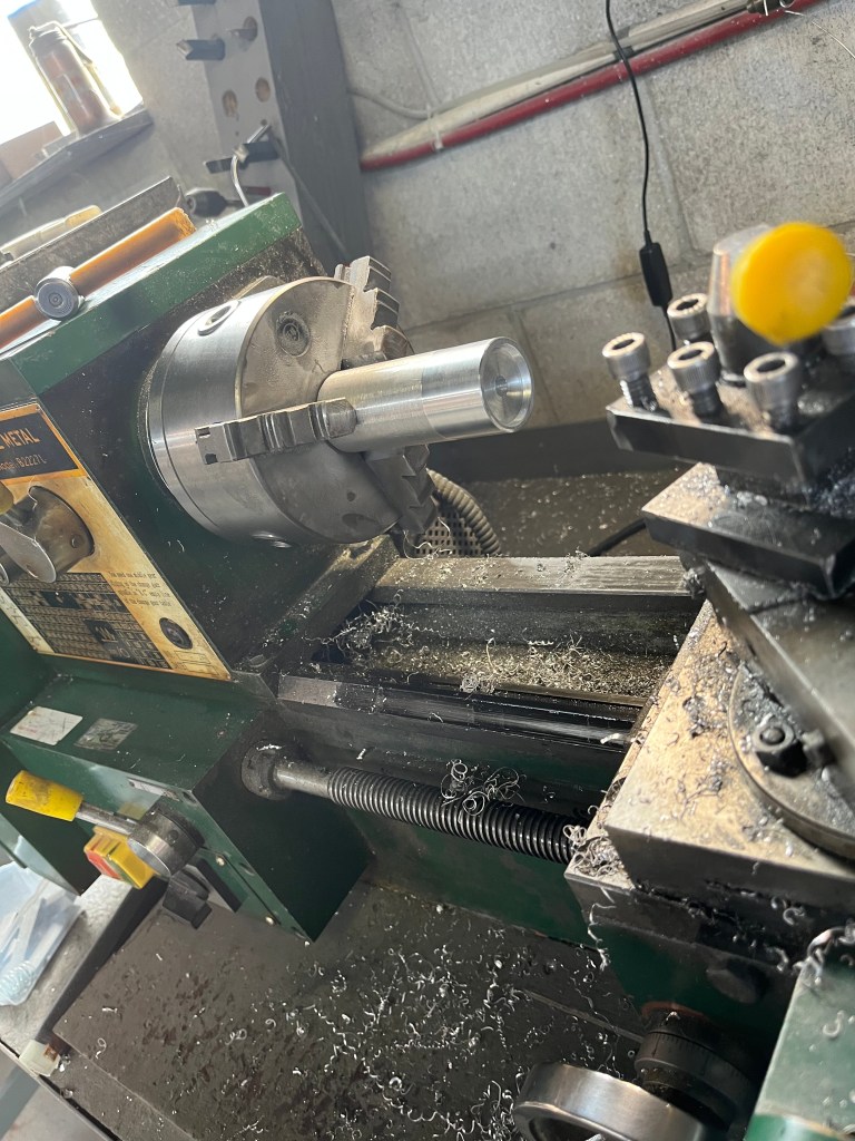
Antenna Winding Station
MADE WHILE WORKING AT VELATRON TECHNOLOGIES
Sept 2025 – Dec 2025
What
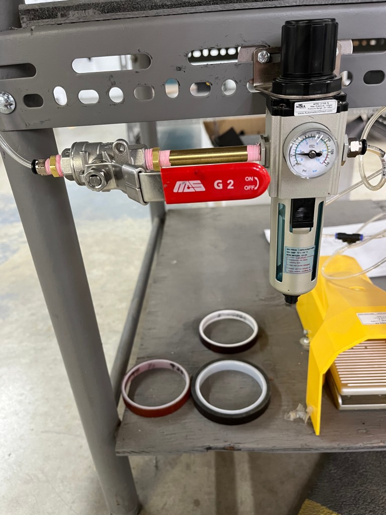
Converted an existing pneumatic roller machine into a reliable, multi-purpose antenna winding station for production use.
How
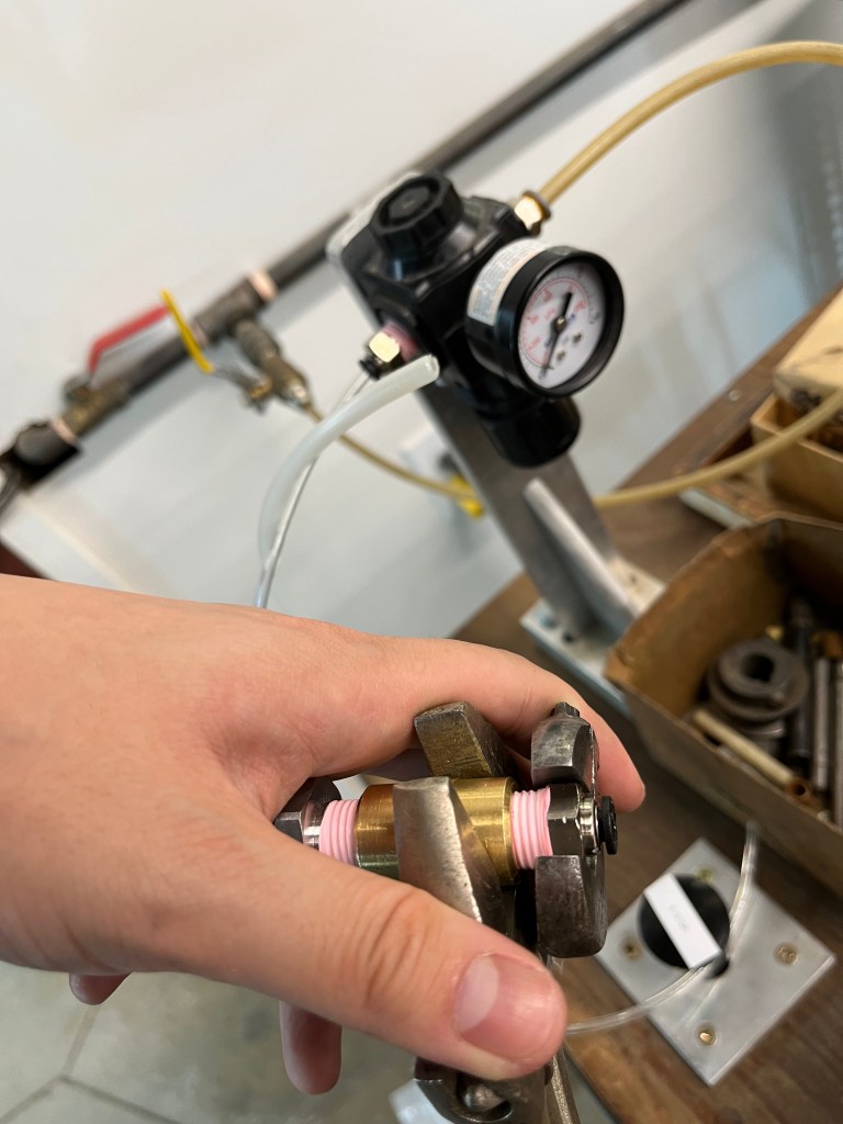
- Upgraded the pneumatic system to improve consistency and control
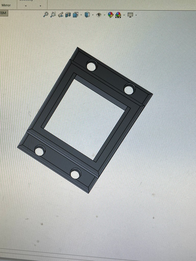
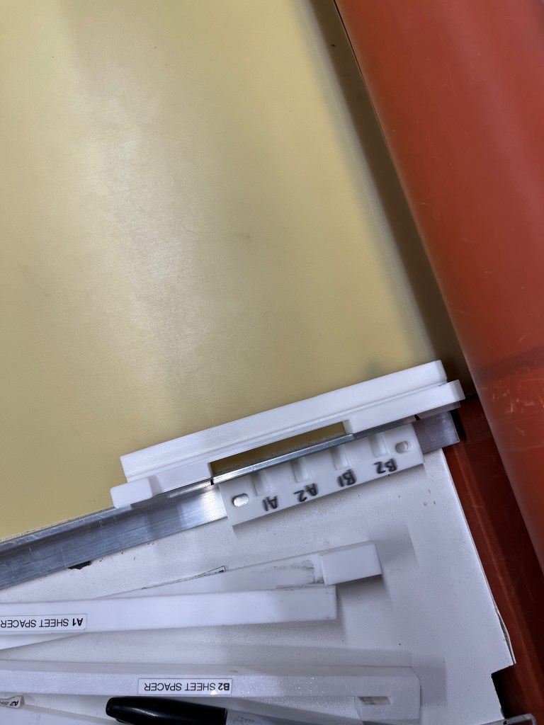
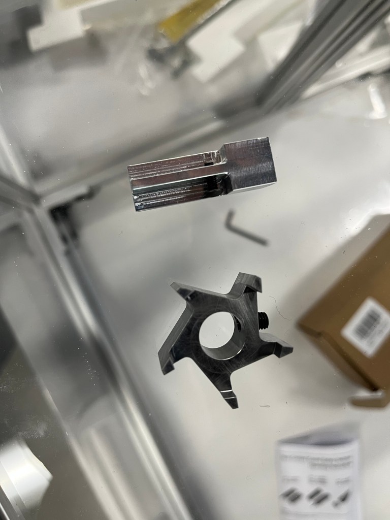
- Designed custom tooling and fixtures to support antenna winding operations
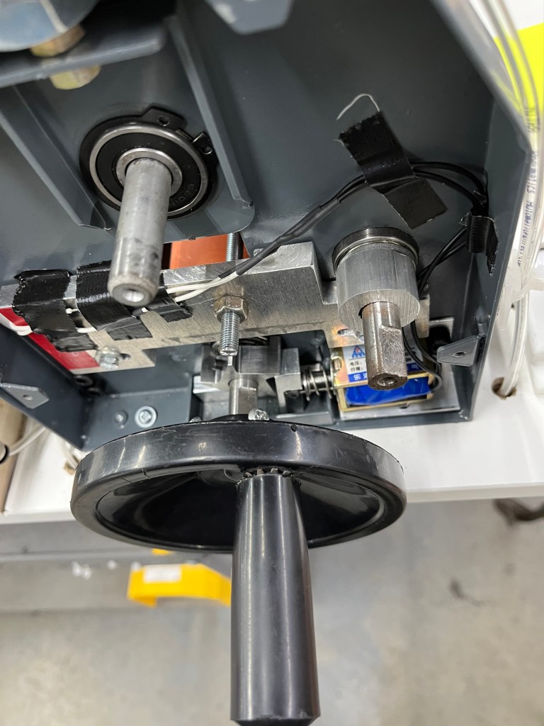
- Integrated an electrical warning and braking system for operator safety
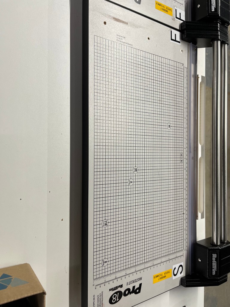
- Developed precision cutting jigs achieving ±0.008” tolerances
- Defined the manufacturing technique and created step-by-step production documentation
- Outlined improvement roadmaps and next steps for future co-op students
Result
- Enabled future scalability toward high-volume manufacturing
- Delivered a production-ready machine suitable for repeat use
- Improved process reliability, safety, and dimensional accuracy
To see all projects done with Velatron, click here
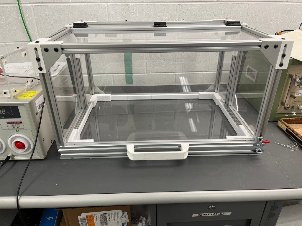
HiPot Testing Enclosure
MADE WHILE WORKING AT VELATRON TECHNOLOGIES
Oct 2025 – Dec 2025
What
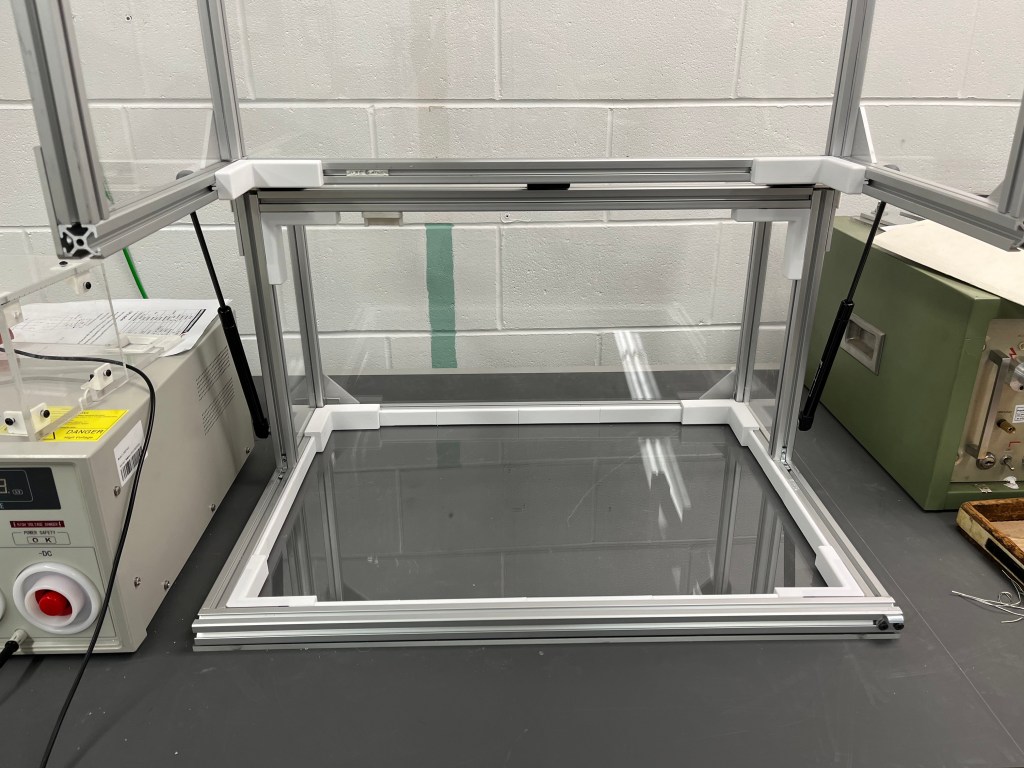
Designed and built a reusable high-voltage safety enclosure for hipot testing in a production environment.
How
- Collaborated with electrical and manufacturing engineers to integrate the enclosure into an existing electrical safety box system
- Researched applicable high-voltage safety requirements and best practices
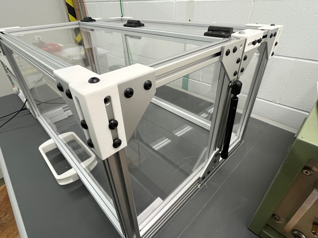
- Independently designed, machined, and assembled the enclosure
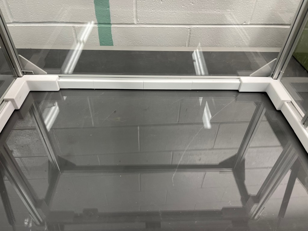
- Integrated electromagnetic safety interlocks to prevent operation when open
- Added gas shock mechanisms for controlled, ergonomic opening and closing
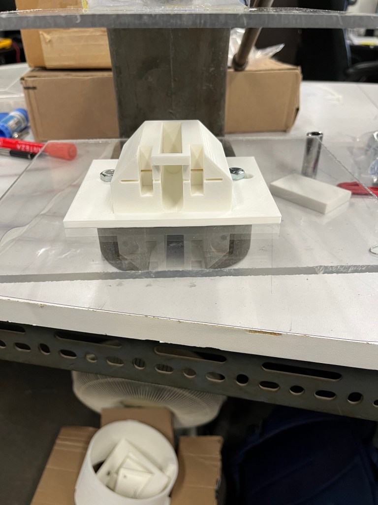
- Designed and 3D-printed a PC-FR insulating base to improve electrical isolation
Result
- Rated for electrical testing up to 20 kV
- Deployed as an active production tool in manufacturing
- Improved operator safety and standardized high-voltage testing procedures
To see all projects done with Velatron, click here
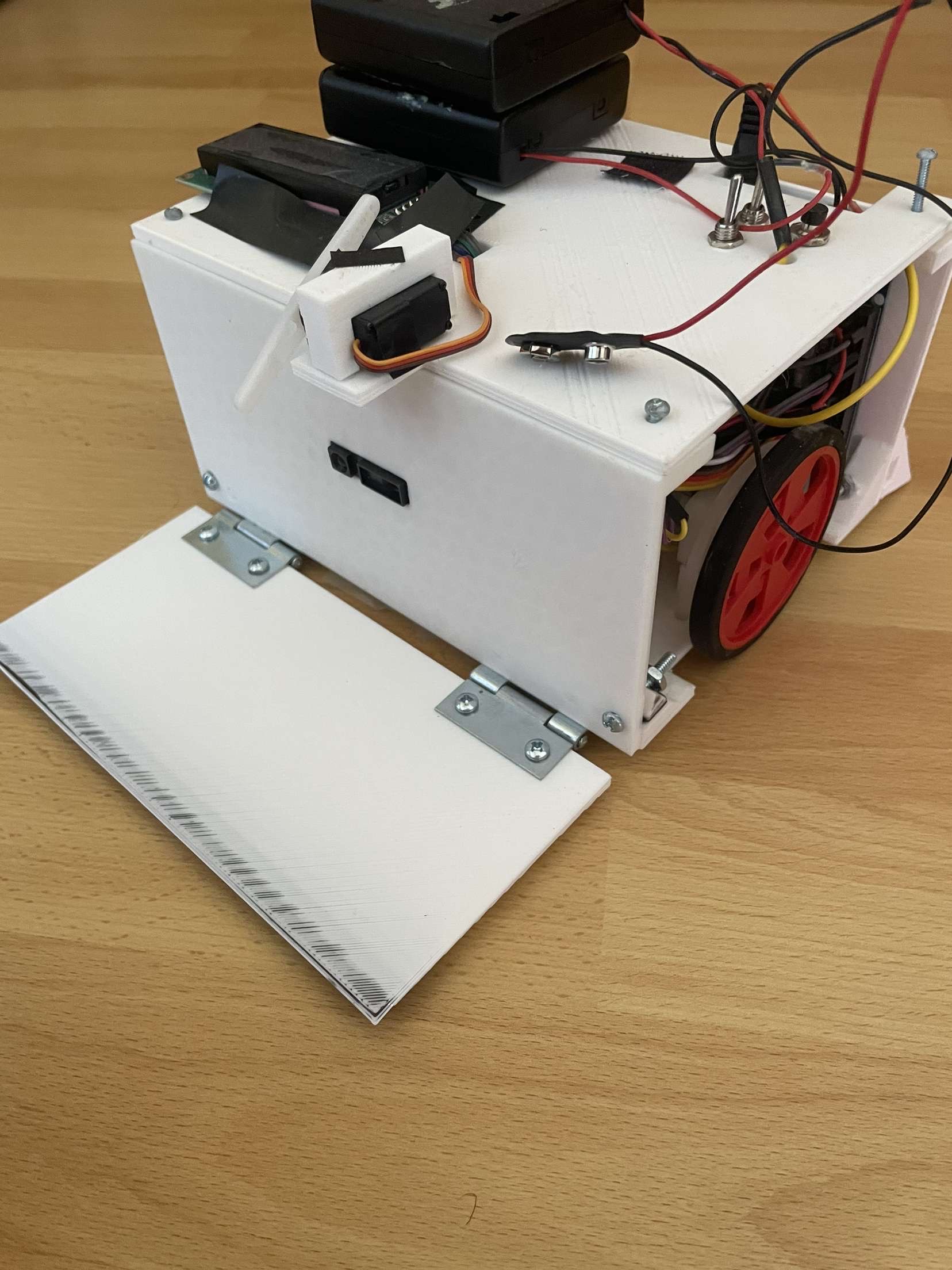
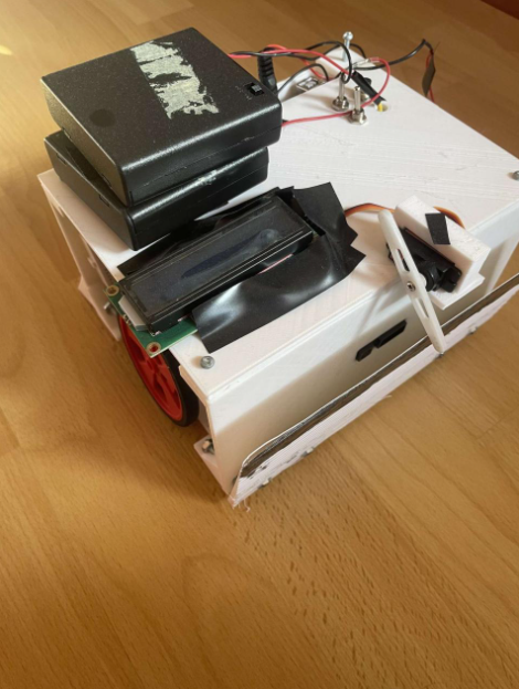
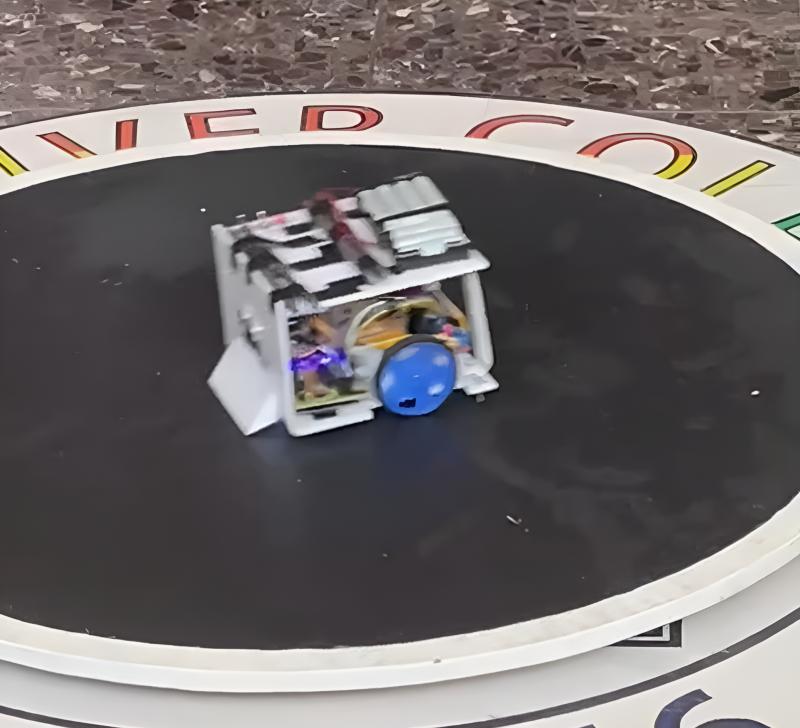
Autonomous Sumo Robot 2.0
April 2024 – June 2024
What
Designed and built an autonomous Arduino-powered sumo robot to detect, engage, and push opponents out of the ring in compliance with competition rules.
How
- Designed a custom 3D-printed chassis with integrated mounting for sensors and actuators
- Used an Arduino as the primary control system, powered by a 9V battery
- Supplied the motor driver with dual AA battery packs for reliable drive power
- Implemented opponent detection using ultrasonic (hypersonic) and Sharp sensors
- Integrated line detection using a superbright LED and phototransistor
- Added a servo-driven automated platform deployment mechanism
- Programmed an LCD interface to display real-time robot states (e.g., ATTACK, FINDING) based on sensor input
Result
- Delivered a competition-ready robot with optimized performance and feedback visibility
- Achieved reliable autonomous detection, decision-making, and engagement behavior
- Demonstrated robust sensor integration and power management


OMEGA Wire Press
MADE WHILE WORKING AT VELATRON TECHNOLOGIES
Mar 2025 – Apr 2025
What
Led the redesign of a coil finishing process to support high-volume production of bent wires for a large manufacturing order.
How
- Evaluated existing 90-degree wire bending methods and identified scalability limitations
- Reviewed the full coil finishing workflow with engineering and production teams
- Proposed an omega-shaped wire bend to enable faster forming, finishing, and cutting
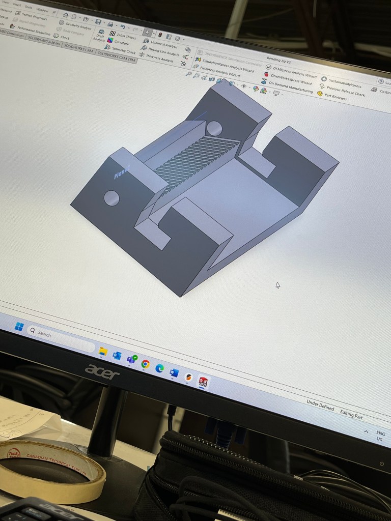
- Designed and built a press-style jig inspired by cookie-cutter manufacturing
- Conducted cost and material waste analysis to validate production viability
Result
- Enabled efficient production of 20,000+ units with improved ergonomics and throughput
- Reduced coil finishing time from 5 minutes to 3 minutes per unit
- Eliminated the primary production bottleneck in a process unchanged for over 15 years
To see all projects done with Velatron, click here
-


Final Bending Jig


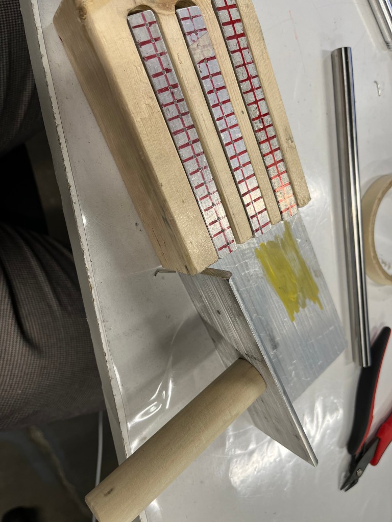

First Iterations of the 90-degree Bending Jig and First Attempt at Omega-Shaped Bending Jig
Spiral Coil Jigs
MADE WHILE WORKING AT VELATRON TECHNOLOGIES
Mar 2025 – Mar 2025
What
Developed a production process and tooling to form a precision wire winding for a medical machine application.
How
- Interpreted customer-supplied drawings with extremely tight tolerances
- Rapidly prototyped multiple jig designs within a one-week timeline
- Evaluated bend accuracy and repeatability across different configurations
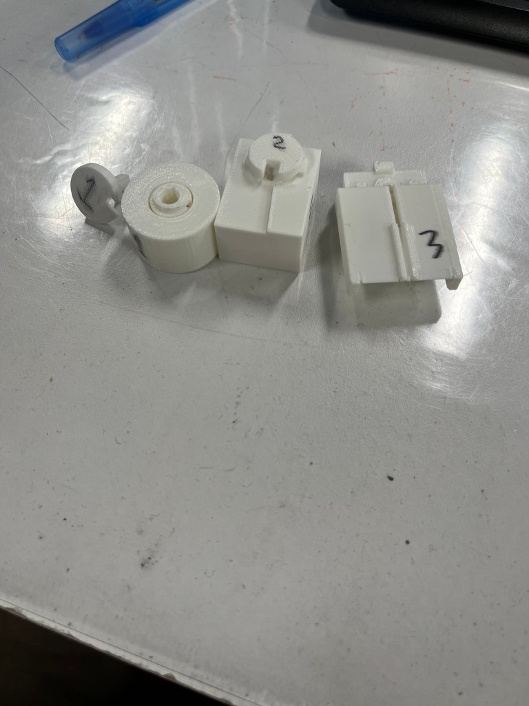
- Finalized a three-jig forming system to achieve the required geometry
- Revised original drawings to adjust tolerances for manufacturability while preserving function
- Submitted updated drawings to the customer for review and approval
Result
- Balanced precision, efficiency, and manufacturability under a tight deadline
- Established the standard production method for this component
- Achieved consistent, repeatable wire geometry within medical-device requirements
To see all projects done with Velatron, click here

Simon Says Game
Sept 2023 – Nov 2023
What
Designed, manufactured, and programmed a “Simon Says” game capable of progressing through 30 levels, inspired by the classic SIMON game.
How
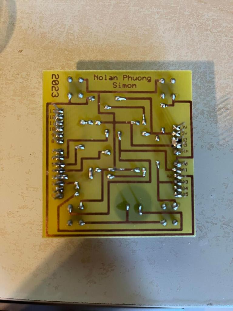
- Designed a custom Arduino shield PCB using ExpressPCB
- Fabricated the PCB, including precision drilling using a drill press
- Populated and soldered all electronic components to complete hardware assembly
- Programmed the game logic in the Arduino IDE to generate and validate random light-and-sound patterns
- Integrated buttons, LEDs, and audio feedback for interactive gameplay
Result
- Combined reliable electronics design with engaging, user-facing functionality
- Delivered a fully functional, standalone electronic game
- Demonstrated end-to-end hardware and software integration


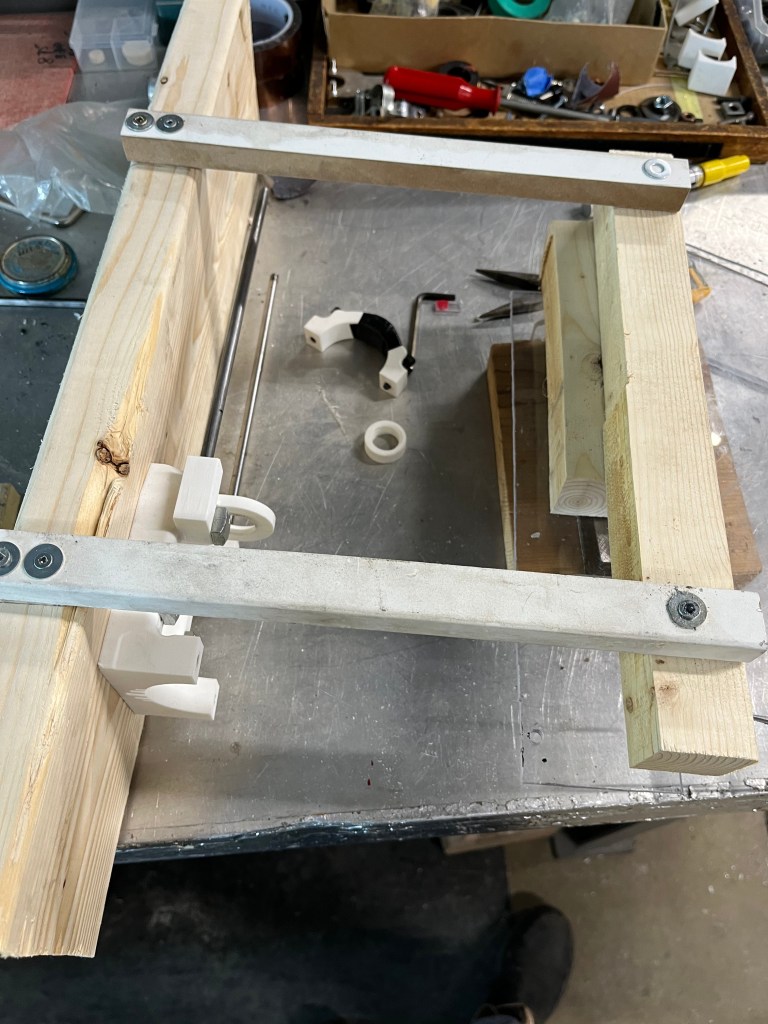
Horizontal Dremel Grinder
MADE WHILE WORKING AT VELATRON TECHNOLOGIES
Feb 2025 – Mar 2025
What
Prototyped a method to precisely remove excess tinned wire flush to a part surface within extremely tight tolerances.
How
- Evaluated conventional cutting methods and ruled them out due to risk of component damage
- Collaborated with the engineering team to identify grinding as the most viable approach
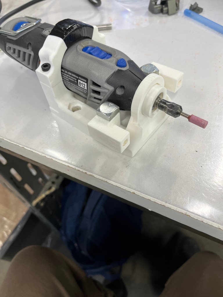
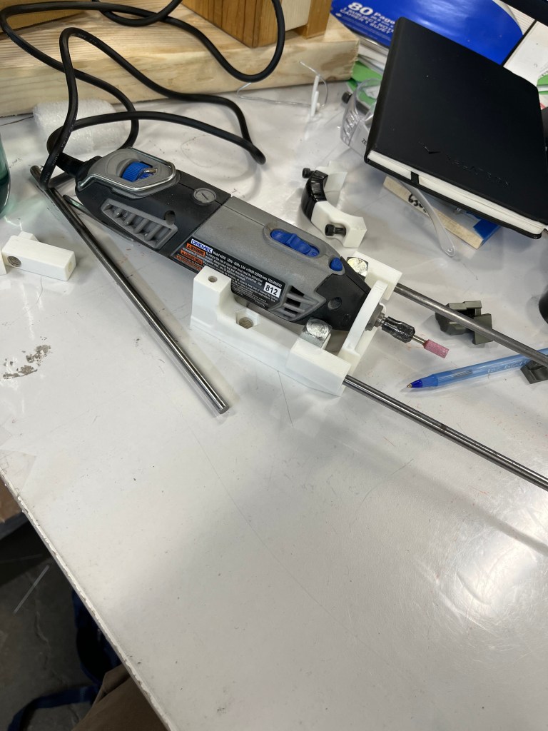
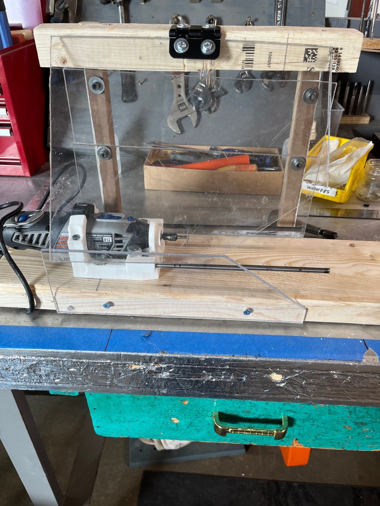
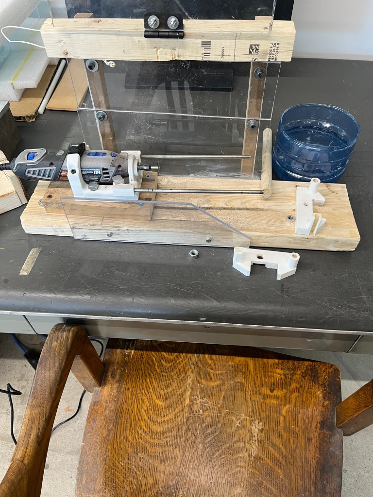
- Designed a custom jig to control wire feed depth and stop position before surface contact
- Integrated a precision rotary tool (Dremel-style) to achieve sub-millimeter accuracy
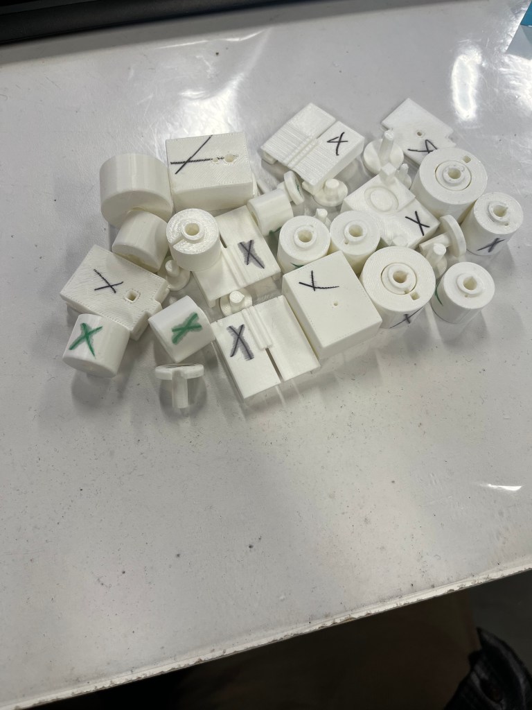
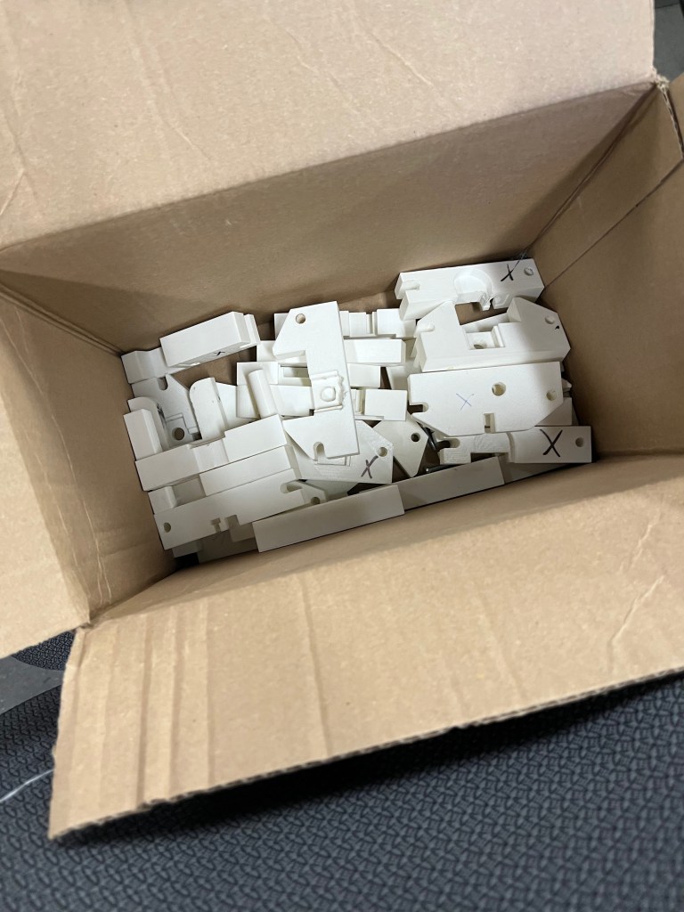
- Iterated over multiple prototypes using 3D-printed parts, scrap wood, and repurposed materials
Result
- Documented limitations and proposed design improvements for future high-volume production
- Achieved reliable wire removal within ±0.1 mm tolerance for sample production
- Delivered a low-cost, functional setup suitable for producing initial customer parts
To see all projects done with Velatron, click here


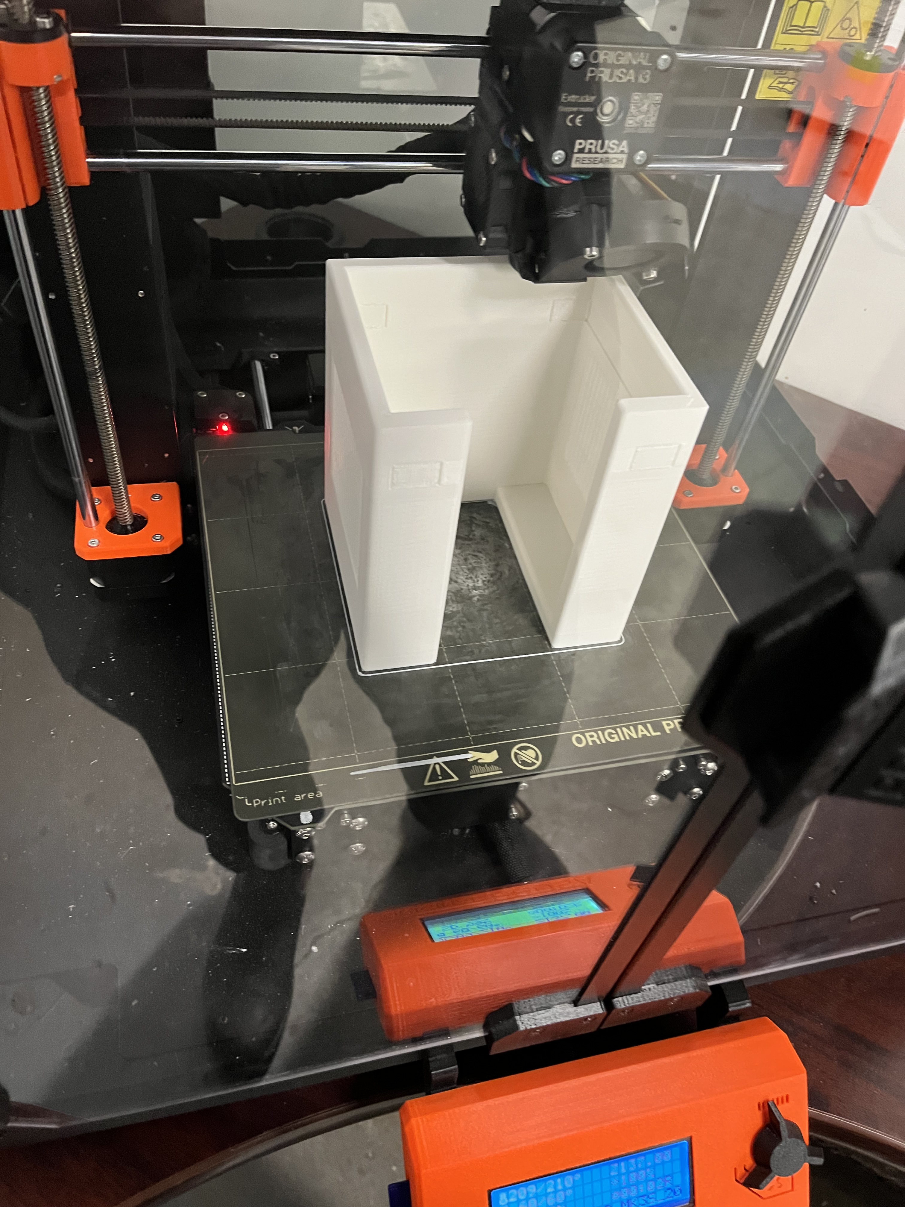
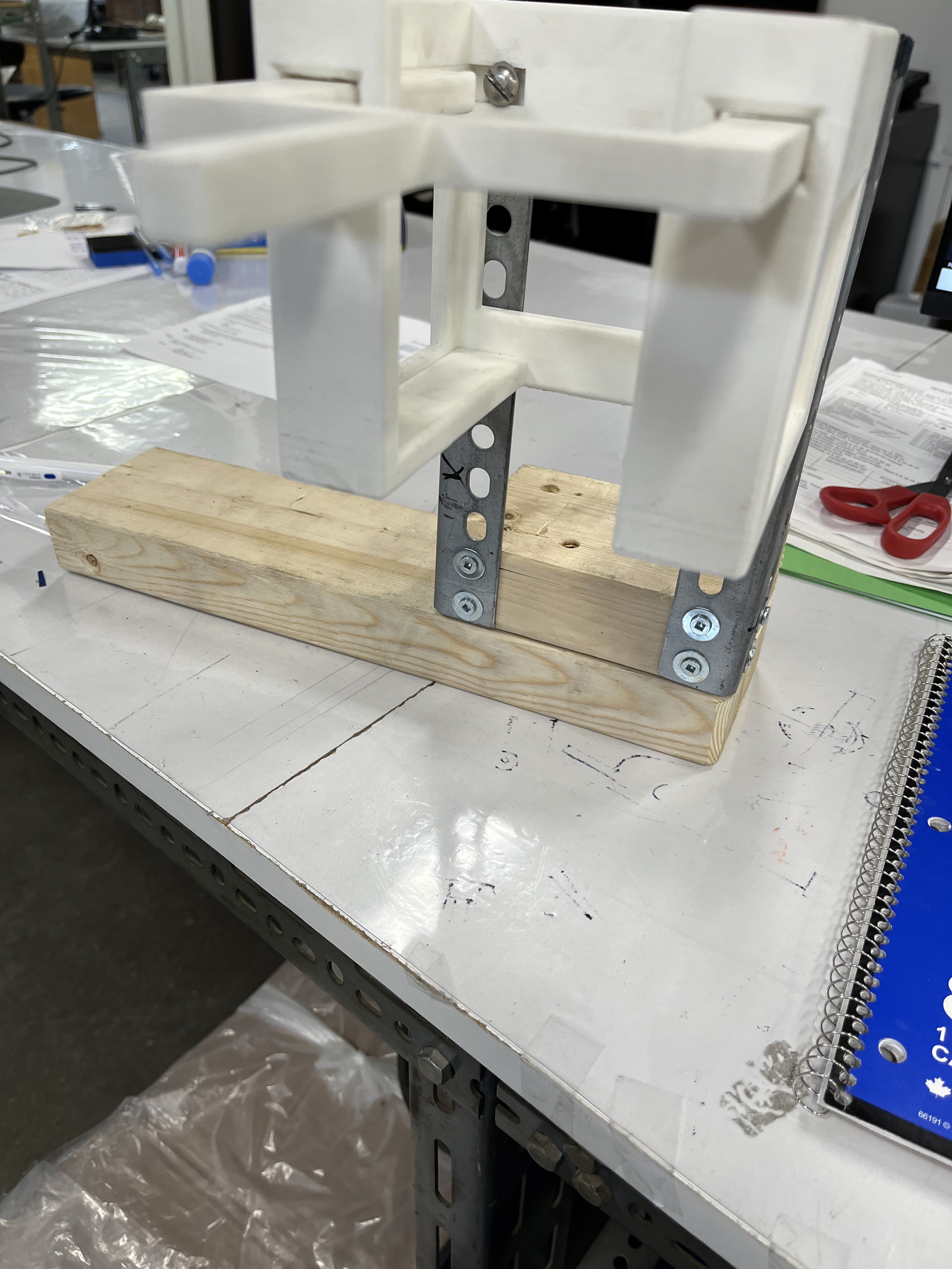
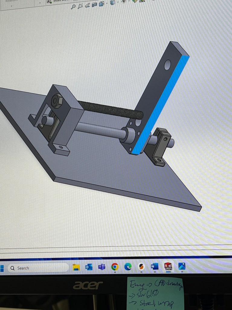
Transformer Wrapping Jig
MADE WHILE WORKING AT VELATRON TECHNOLOGIES
Jan 2025 – Feb 2025
What
Designed a custom jig to assist production workers in wrapping wire around transformer cores accurately and efficiently.
How
- Designed a jig that elevates and secures the core, enabling smooth wire threading from both the top and bottom
- Integrated a telescopic end holder to anchor wire at a precise distance for consistent length control
- Iterated on multiple prototypes to resolve issues with holder stability and fork height
- Added adjustable levelers to accommodate multiple core sizes
- Fabricated components using 3D-printed PLA, repurposed materials, and scrap wood to minimize cost
Result
- Reduced wrapping time from 20 minutes to 15 minutes per unit
- Improved repeatability and ease of use for production workers
- Enhanced workflow efficiency for a time-sensitive transformer order
To see all projects done with Velatron, click here
-
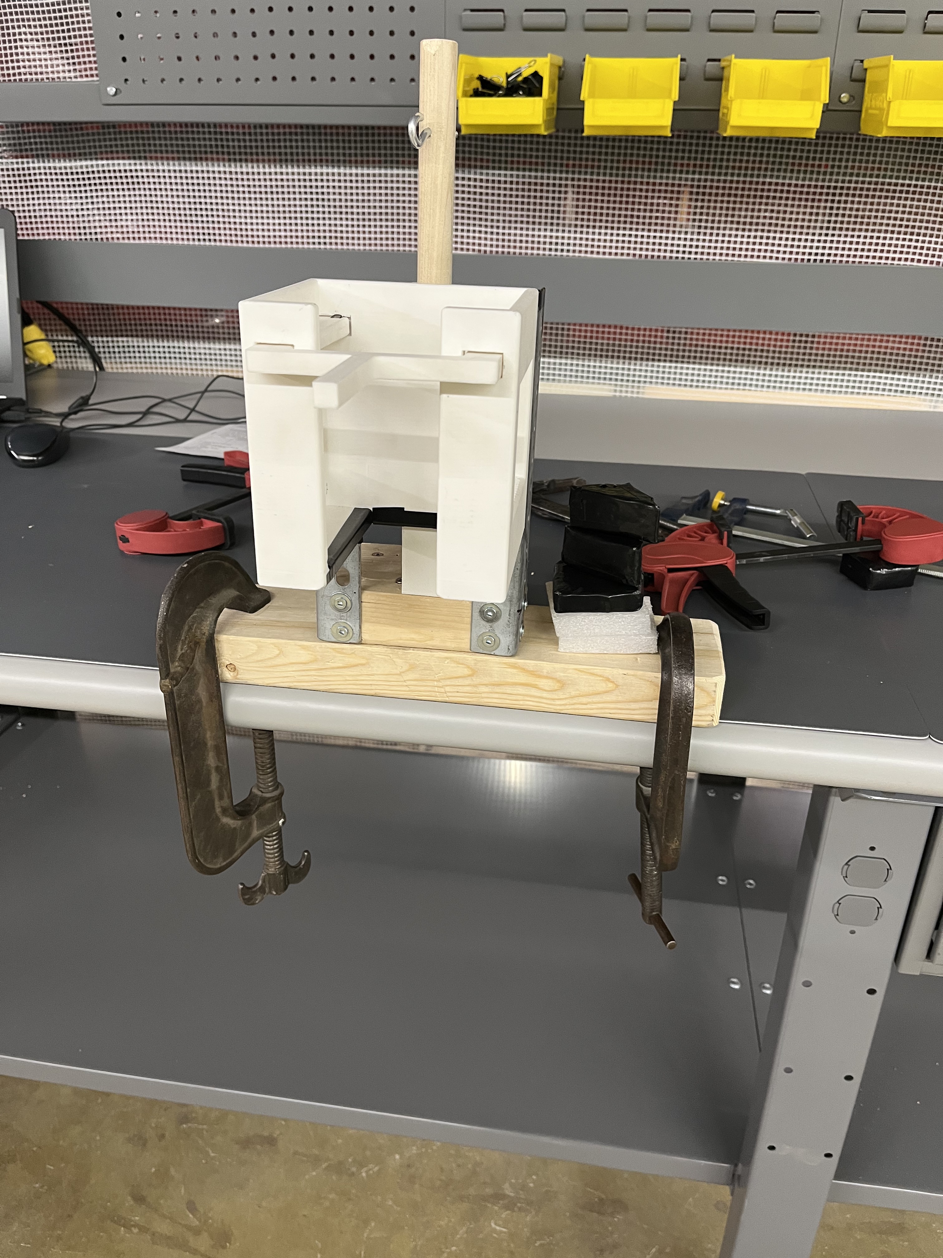


Final product


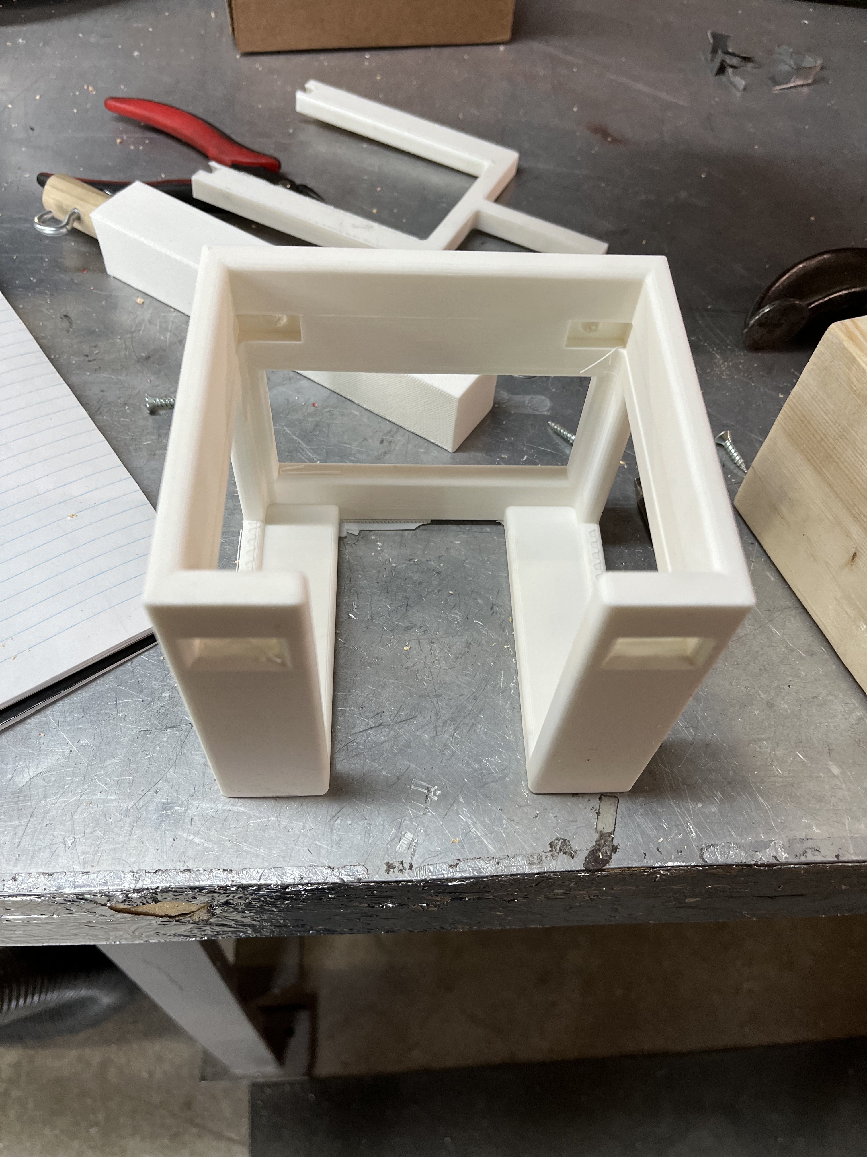

First iterations/prototypes for the jig
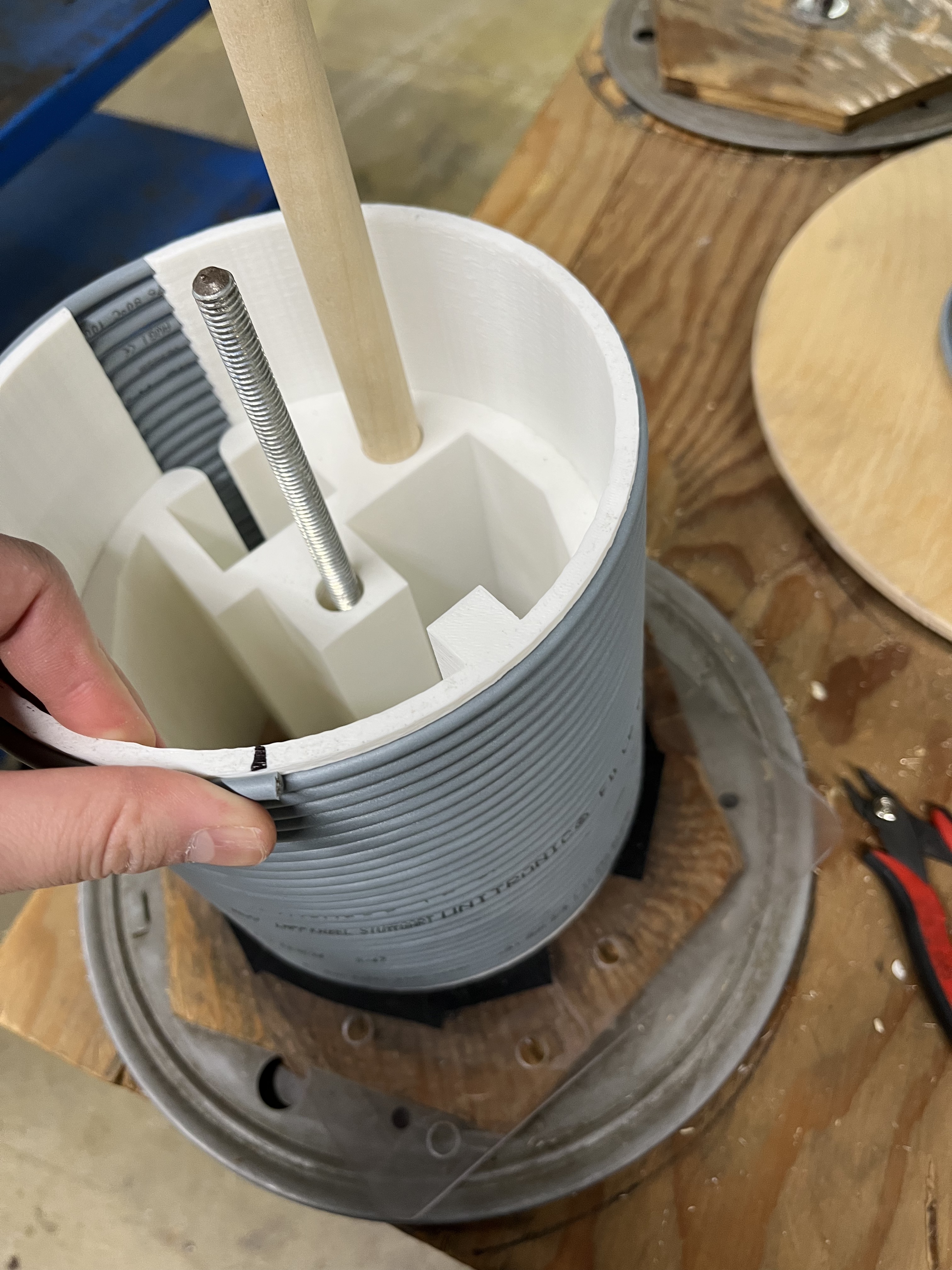
Wire “Salad Spinner” Jig
MADE WHILE WORKING AT VELATRON TECHNOLOGIES
Jan 2025 – Jan 2025
What
Redesigned the wire-wrapping process to produce consistent, tangle-free wire lengths for production use.
How
- Identified inefficiencies in the manual spool unwinding and rewrapping process
- Prototyped multiple 3D-printed designs to automate and standardize wrapping
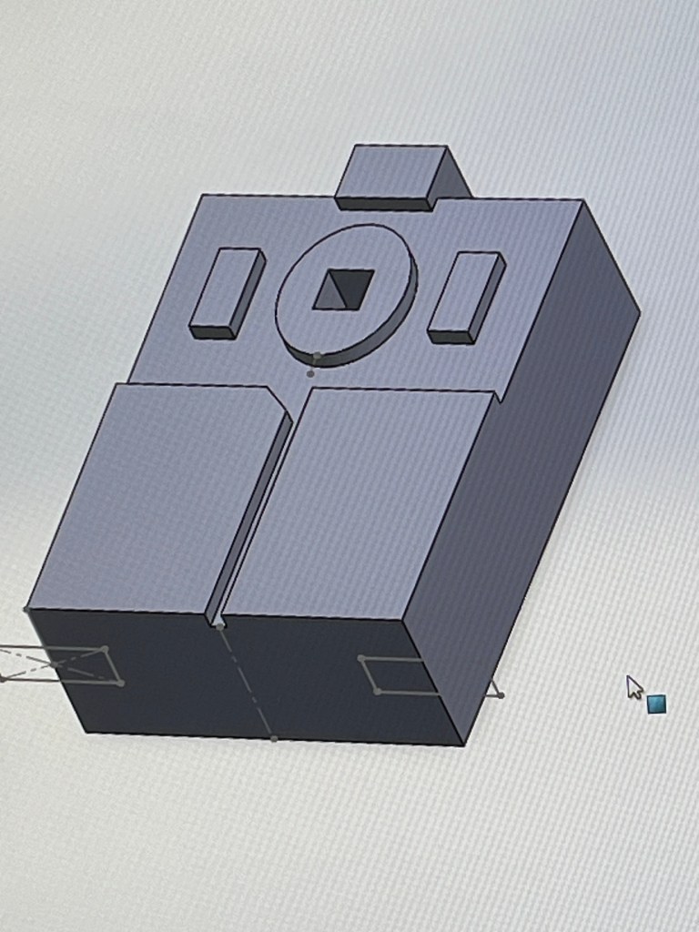
- Designed a threaded sliding ring with guided ridges in SOLIDWORKS for precise coil spacing
- Replaced unreliable mechanical counters with visual reference markers for repeatable lengths
Result
- Reduced wire-wrapping time from 8 minutes to 3 minutes per unit
- Eliminated tangling and length inconsistencies
- Improved throughput and reliability for high-volume production
To see all projects done with Velatron, click here
-
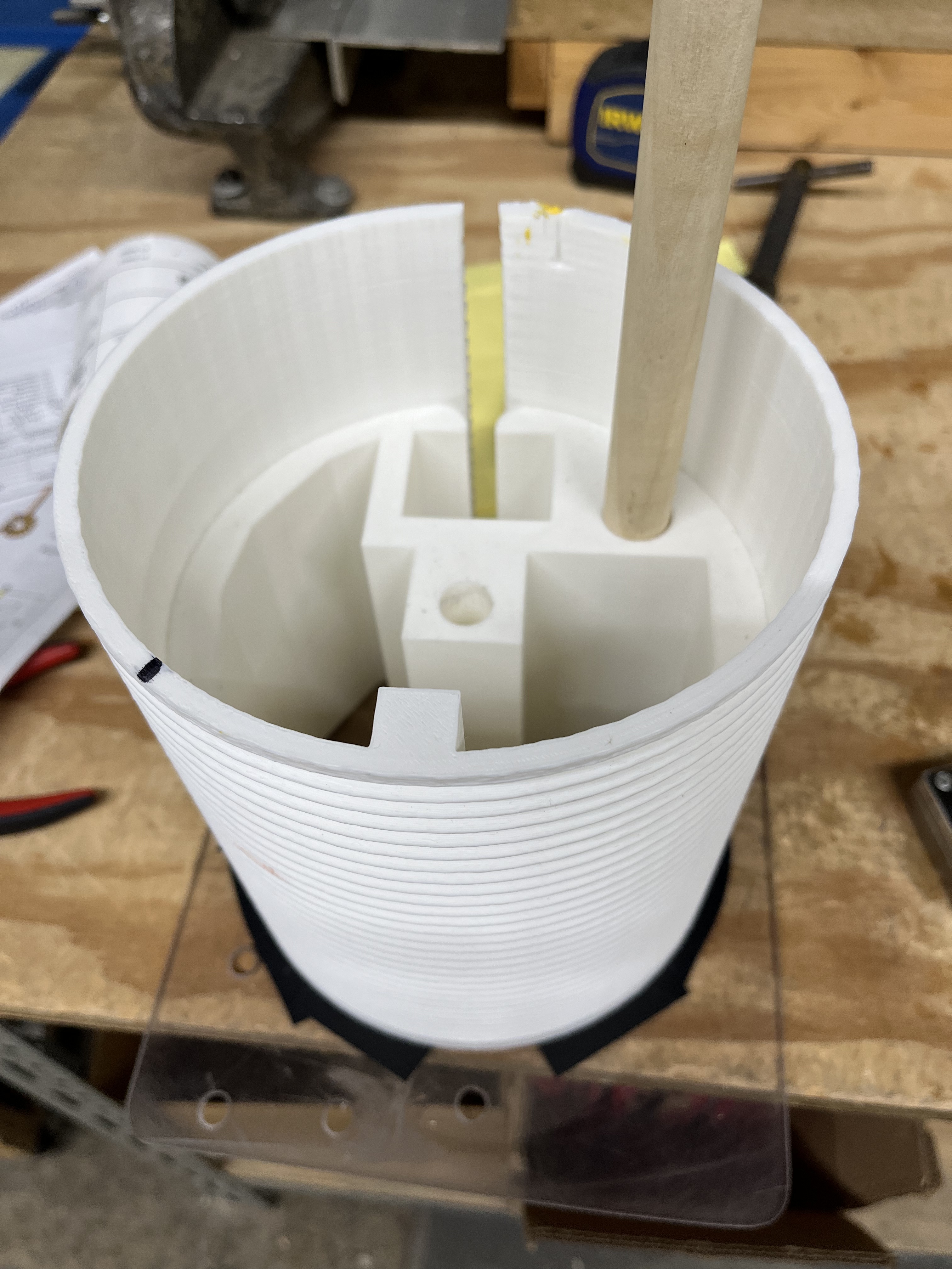

Final Product


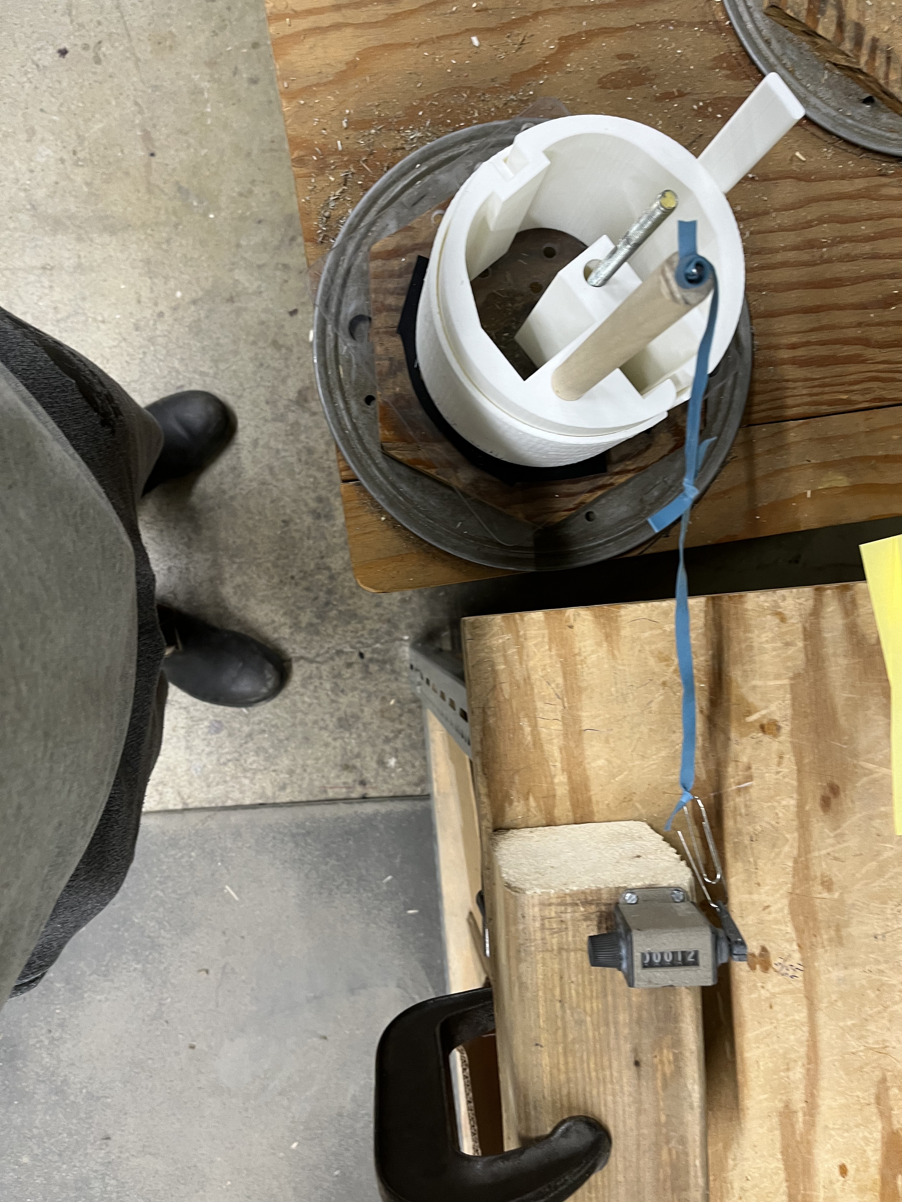
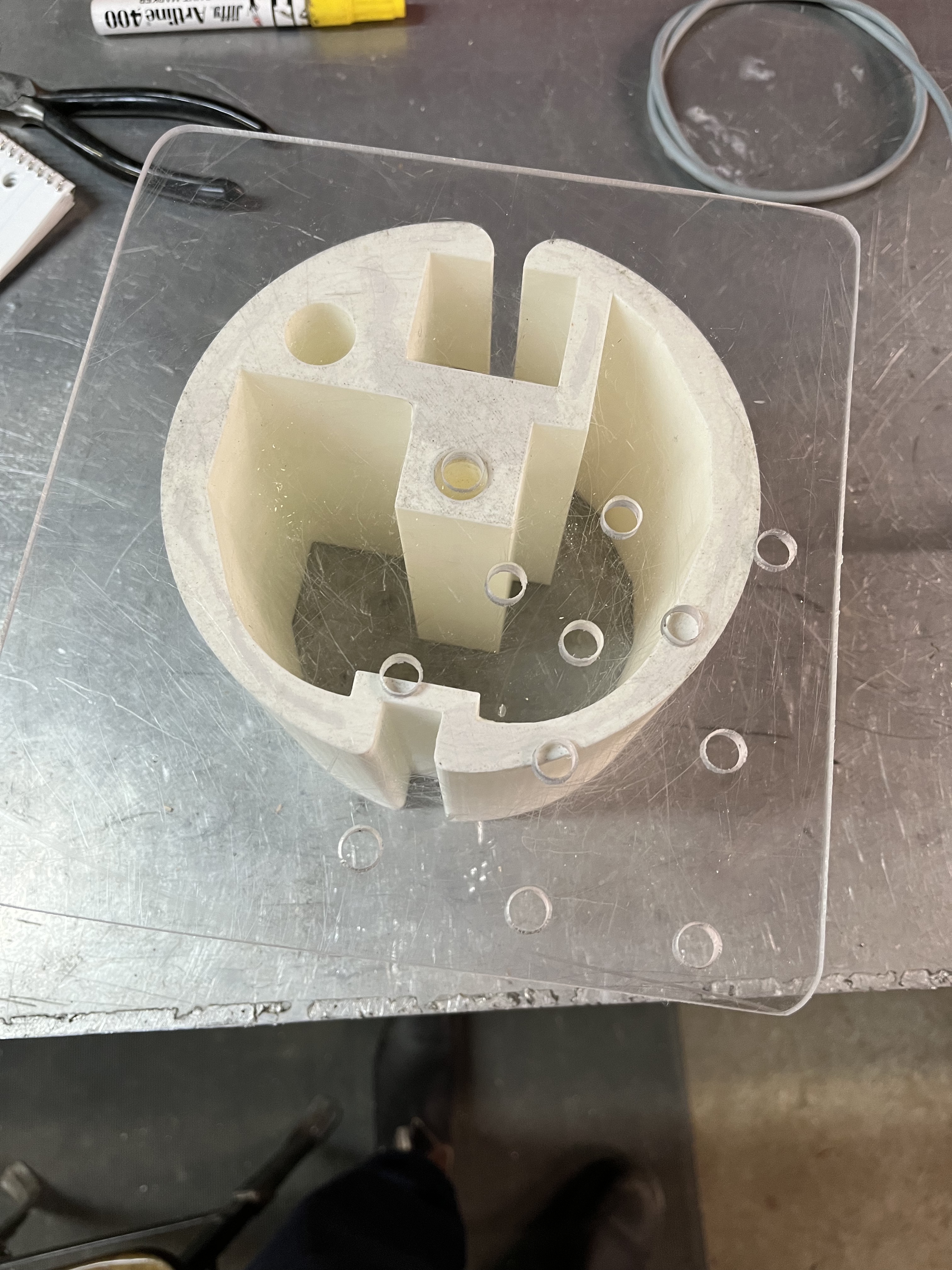

First iterations
Conveyor Belt Tensioner
Mar 2025 – Mar 2025
What
Designed and built a belt tensioner for a custom conveyor system used in the manufacturing of a specialized part.
How
- Designed the tensioner and full assembly in SOLIDWORKS
- Salvaged linear ball bearings and steel rods from decommissioned equipment to reduce cost
- 3D printed prototype components to validate fit, motion, and alignment
- Reviewed the design with a senior engineer before finalizing
- Delivered final CAD files to a machinist for future fabrication
Result
- Enabled smooth belt tracking and readiness for long-term production use
- Produced a cost-effective, robust belt tensioning solution
To see all projects done with Velatron, click here


Autonomous Sumo Robot 1.0
April 2023 – June 2023
What
Developed the first iteration of an Arduino-powered sumo robot for a competitive push-out robotics challenge.
How
- Designed and fabricated a custom chassis from scrap plastic using heat forming techniques
- Designed a custom PCB shield to integrate line detection using a superbright LED and phototransistor
- Implemented opponent detection using an ultrasonic (hypersonic) sensor
- Integrated a motor driver for precise speed and directional control
Result
- Established a solid hardware and electronics foundation for future iterations
- Produced a functional, competition-ready prototype
- Demonstrated reliable boundary detection and opponent tracking


ME100 Design Projects
These designs were created on SOLIDWORKS for University of Waterloo ME100 student design course.

Engineering Keychain
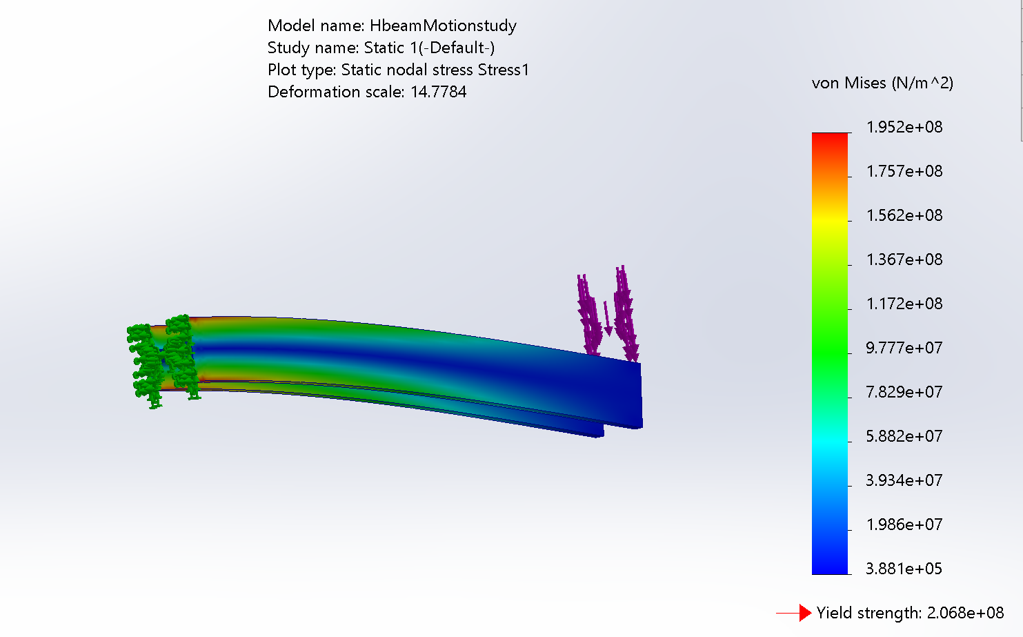
H-Beam AISI 304 Steel Static Study

